
このチュートリアルは武蔵野美術大学通信教育課程授業用に作成したものです。
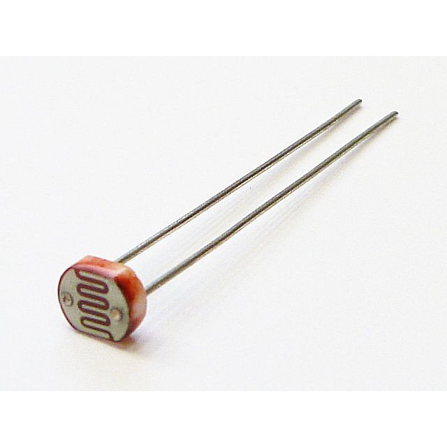
今回はCDSセルを使った光センサーの利用方法です。CDSセルは光の量で抵抗値が変わるセンサーです。明るいと抵抗値が小さくなり、暗くいと抵抗値が大きくなります。
配線
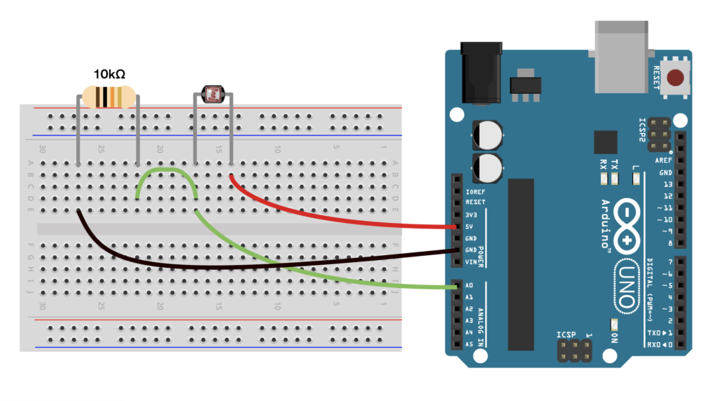
CDSセルは光をセンシングするので外の環境(屋外・屋内・暗い部屋・明るい部屋)などで値が大きく変わります。何かものをつくるときは、実際にインストールする環境の光を意識してみてください。
プログラム
今回はexampleの「AnalogReadSerial」を試してみます。
/*
  AnalogReadSerial

  Reads an analog input on pin 0, prints the result to the Serial Monitor.
  Graphical representation is available using Serial Plotter (Tools > Serial Plotter menu).
  Attach the center pin of a potentiometer to pin A0, and the outside pins to +5V and ground.

  This example code is in the public domain.

  https://www.arduino.cc/en/Tutorial/BuiltInExamples/AnalogReadSerial
*/

// the setup routine runs once when you press reset:
void setup() {
  // initialize serial communication at 9600 bits per second:
  Serial.begin(9600);
}

// the loop routine runs over and over again forever:
void loop() {
  // read the input on analog pin 0:
  int sensorValue = analogRead(A0);
  // print out the value you read:
  Serial.println(sensorValue);
  delay(1);        // delay in between reads for stability
}
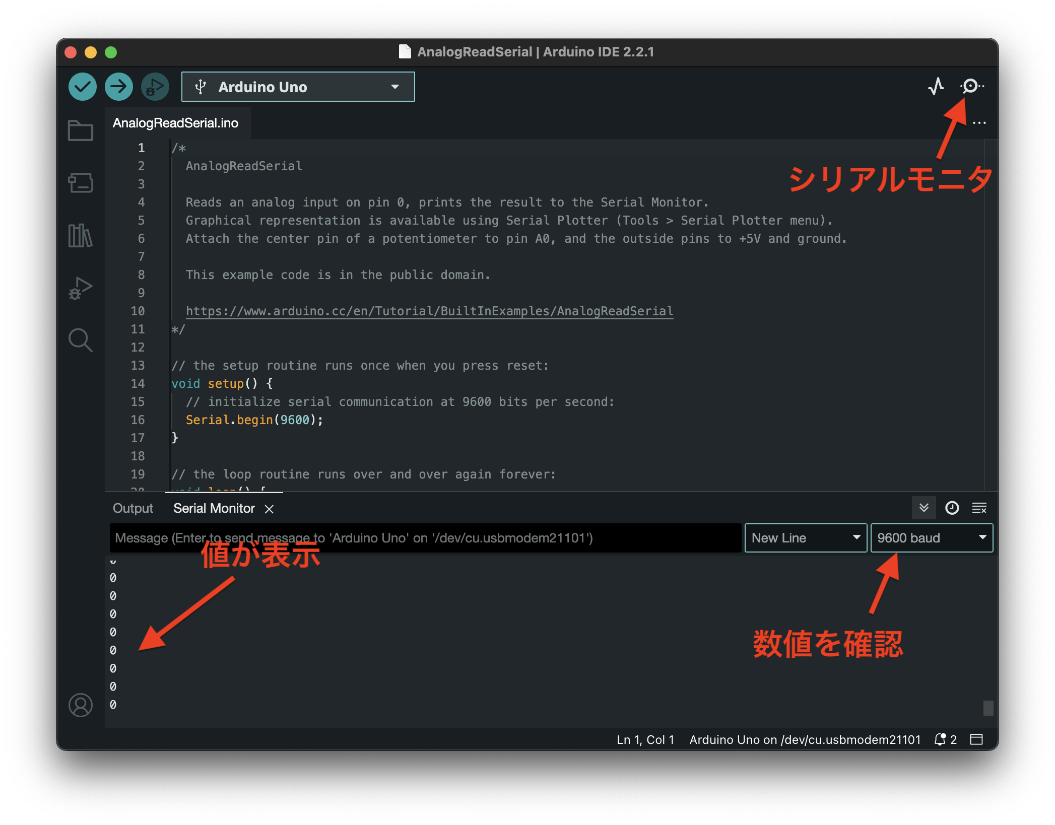
CDSセルライトで光を当ててみたり、手で覆って影を落としてみたりしてみてください。
シリアルモニターに表示される値が変化するはずです。値の変化に合わせて条件分岐などで振る舞いをプログラムしてみてください
光に対応させる
せっかくなので、センサーで取得した値をLEDに反映させてみましょう。
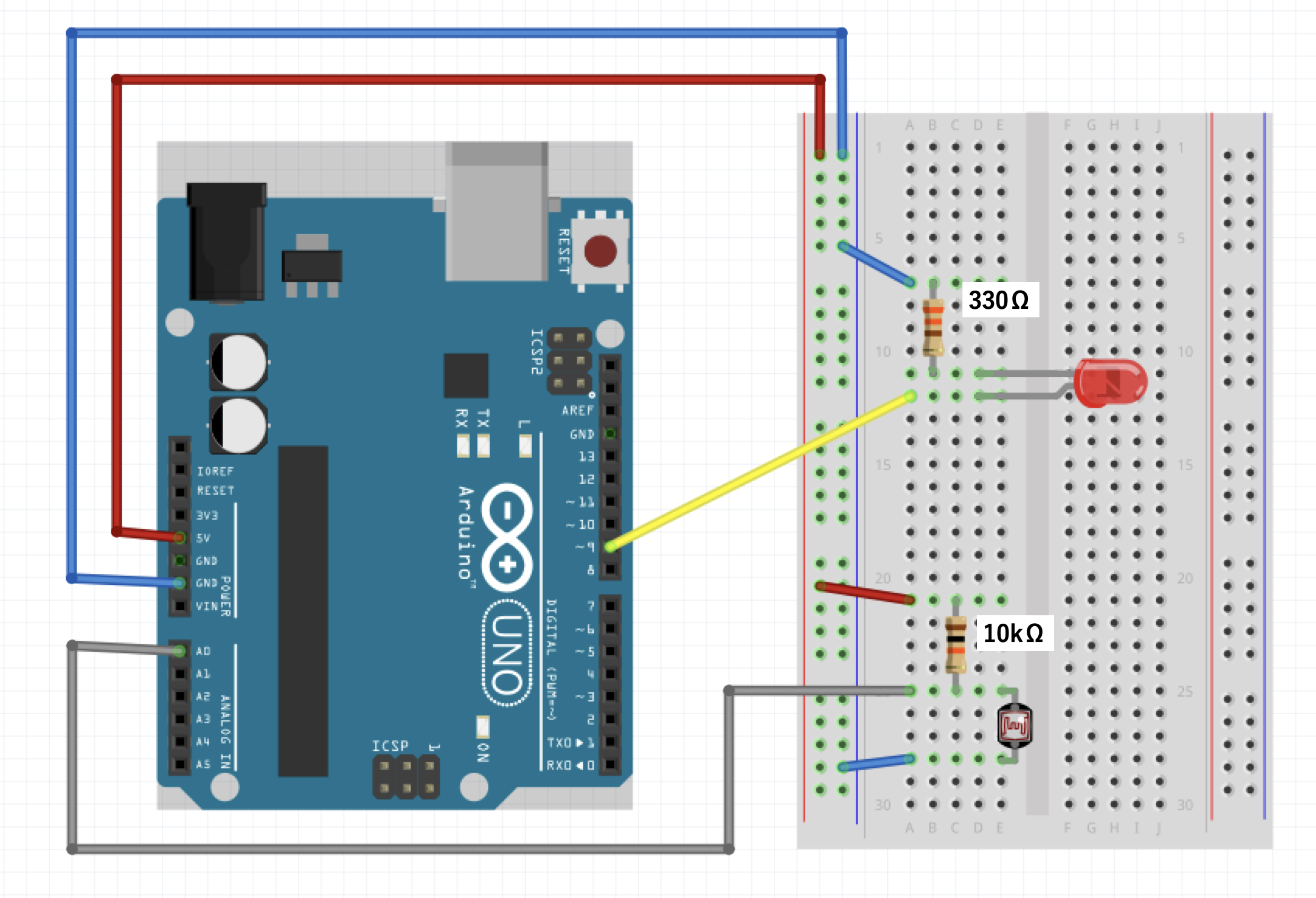
上記セッティングを行います。スケッチの例から「03.Analog/AnalogInOutSerial」を開きます。
/*
  Analog input, analog output, serial output

  Reads an analog input pin, maps the result to a range from 0 to 255 and uses
  the result to set the pulse width modulation (PWM) of an output pin.
  Also prints the results to the Serial Monitor.

  The circuit:
  - potentiometer connected to analog pin 0.
    Center pin of the potentiometer goes to the analog pin.
    side pins of the potentiometer go to +5V and ground
  - LED connected from digital pin 9 to ground through 220 ohm resistor

  created 29 Dec. 2008
  modified 9 Apr 2012
  by Tom Igoe

  This example code is in the public domain.

  https://www.arduino.cc/en/Tutorial/BuiltInExamples/AnalogInOutSerial
*/

// These constants won't change. They're used to give names to the pins used:
const int analogInPin = A0;  // Analog input pin that the potentiometer is attached to
const int analogOutPin = 9;  // Analog output pin that the LED is attached to

int sensorValue = 0;  // value read from the pot
int outputValue = 0;  // value output to the PWM (analog out)

void setup() {
  // initialize serial communications at 9600 bps:
  Serial.begin(9600);
}

void loop() {
  // read the analog in value:
  sensorValue = analogRead(analogInPin);
  // map it to the range of the analog out:
  outputValue = map(sensorValue, 0, 1023, 0, 255);
  // change the analog out value:
  analogWrite(analogOutPin, outputValue);

  // print the results to the Serial Monitor:
  Serial.print("sensor = ");
  Serial.print(sensorValue);
  Serial.print("\t output = ");
  Serial.println(outputValue);

  // wait 2 milliseconds before the next loop for the analog-to-digital
  // converter to settle after the last reading:
  delay(2);
}
上記コードをアップロードしてみてください。
すると、光センサーが暗くなるのに呼応してLEDが明滅します。ただ、環境によってはとても変化がわかりにくいかもしれません。そんなときは「constrain」関数を使ってみましょう
const int analogInPin = A0;
const int analogOutPin = 9;

int sensorValue = 0;
int outputValue = 0;

void setup() {
  Serial.begin(9600);
}

void loop() {
  sensorValue = analogRead(analogInPin);

  sensorValue = constrain(sensorValue,200,760);

  outputValue = map(sensorValue, 200, 760, 0, 255);

  analogWrite(analogOutPin, outputValue);


  Serial.print("sensor = ");
  Serial.print(sensorValue);
  Serial.print("\t output = ");
  Serial.println(outputValue);

  delay(2);
}
上記が変更したコードです。
Constrain関数は指定の変数をある範囲に収める関数です。
「sensorValue」の範囲を下限200,上限760に設定します。
数字は自分の環境で、センサーに触れてない状態の値を上限、手で覆ったときの値を下限に設定するとわかりやすいです。
これで、200より下の数値が取得されても200という値を返し、760よりも上でも760と返す形になります。
意図しない数値が取得されると予想とは違う振る舞いになってしまう可能性があるためこの関数で規定することで範囲を限定できます。
また、上記に並行してMap関数を調整します。「constrain」で絞った範囲に変更します。
どうでしょうか?光り方がよりわかりやすくなったでしょうか?色々と数値を調整して使ってみてください。